
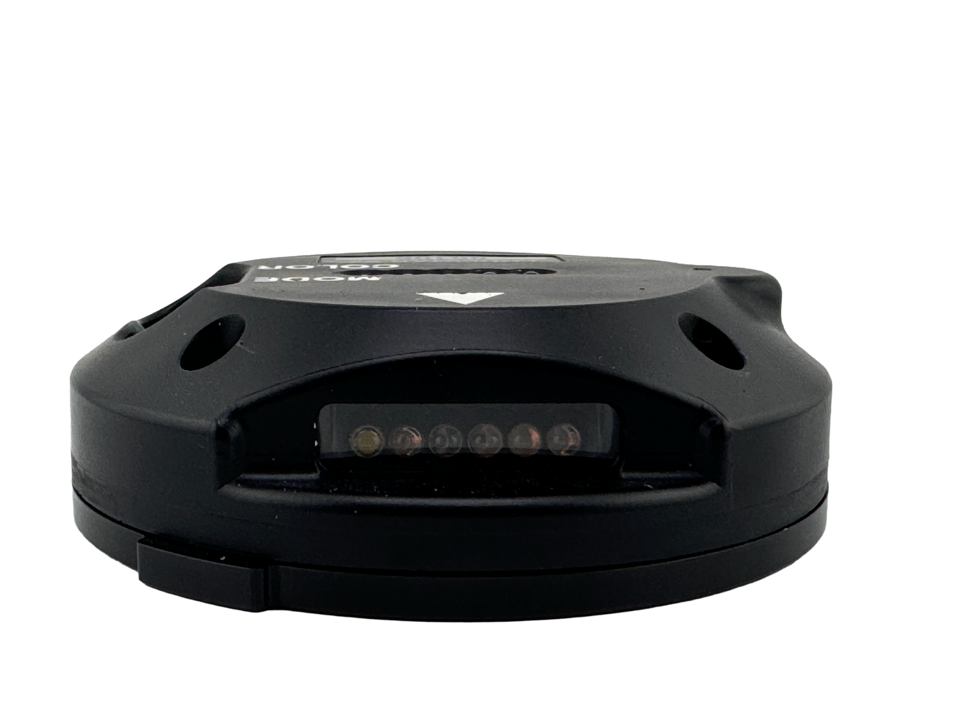
LodeStar® V2
Introducing the LodeStar V2, a revolutionary remote marking system with vibrant LED lights. Perfect for airfields and drop zones, it offers both steady and flashing illumination for maximum visibility. Designed for versatility, the LodeStar V2 adapts to any mission, ensuring safety and clarity in every operation. With customizable lighting options and an intuitive interface, the LodeStar V2 makes it easy to switch settings on the fly, keeping you prepared for any situation.
Multiple Modes
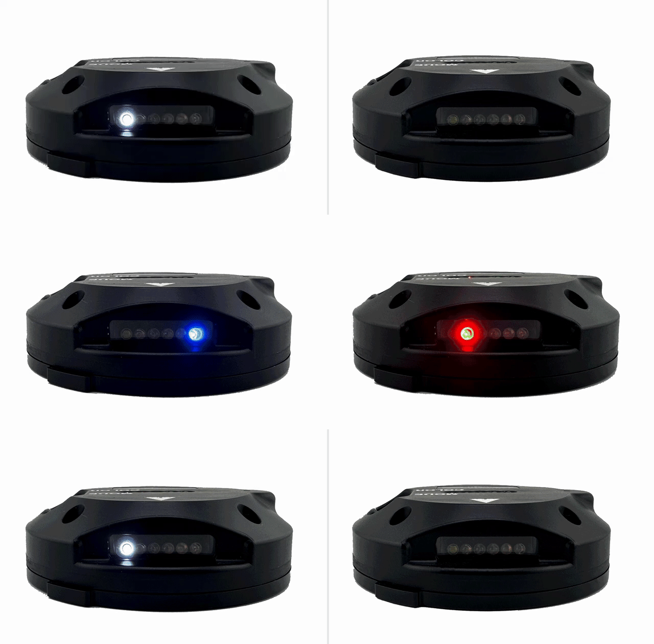
The mode button cycles the unit through the modes: These modes are customer specific and may be defined by each customer at the time of manufacture. A “mode” can be whether the light output is steady or flash, or the combination of arrays in use, i.e., front and rear on with top off, top and rear with front off, top only…etc.)
The color button cycles the unit through the various colors (including IR)
• IR / Red / White / Blue / Green / Back to IR
Battery Powered
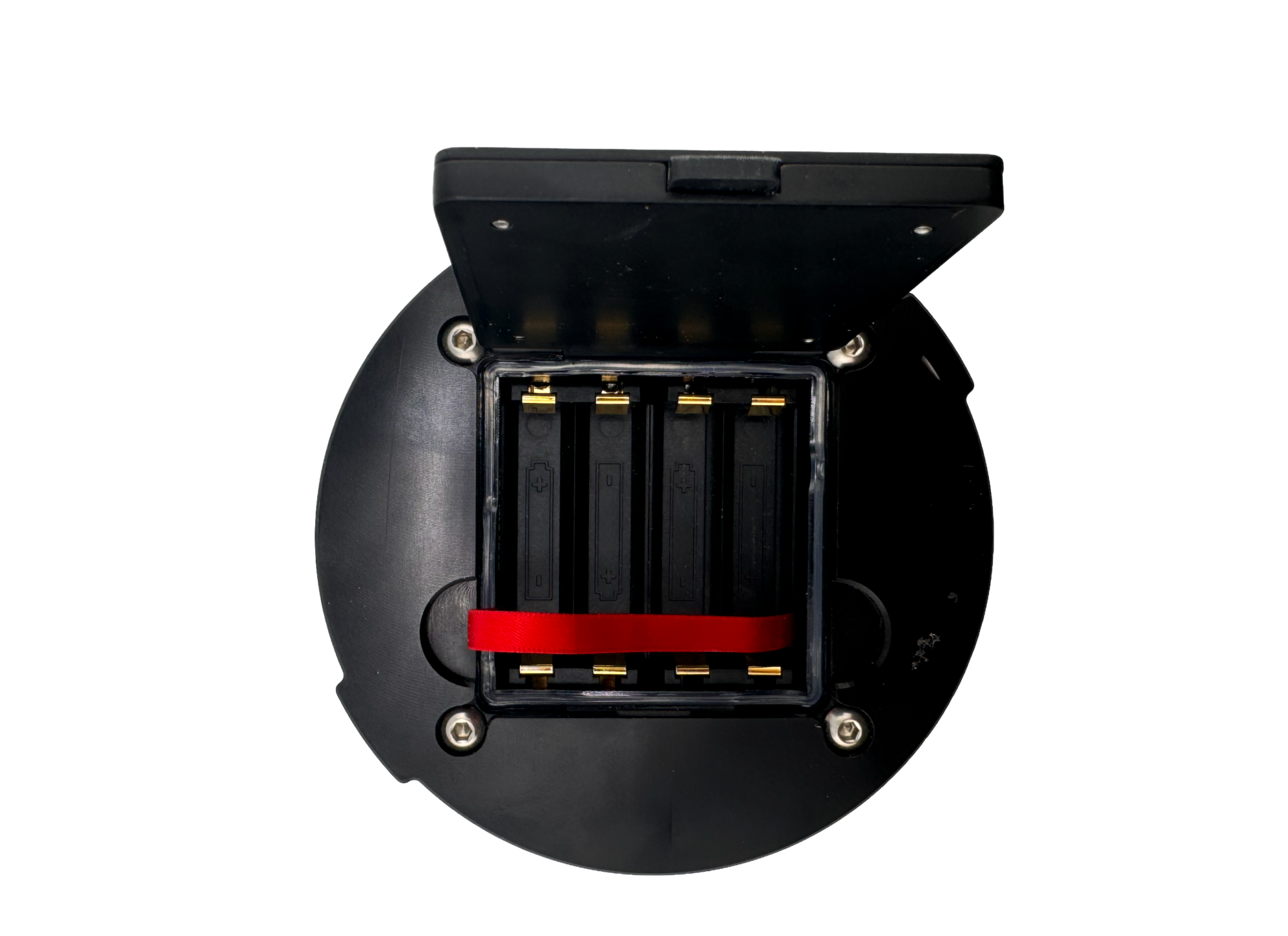
The Lodestar V2 uses (4) AA batteries. Designed to accommodate lithium batteries.
Durable Design
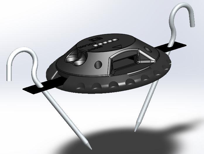
The unit housing is made from proprietary glass reinforced polymer designed to resist mechanical effects of rollover by heavy wheeled machinery or aircraft, e.g., C-130 & C-17.
LED Lights
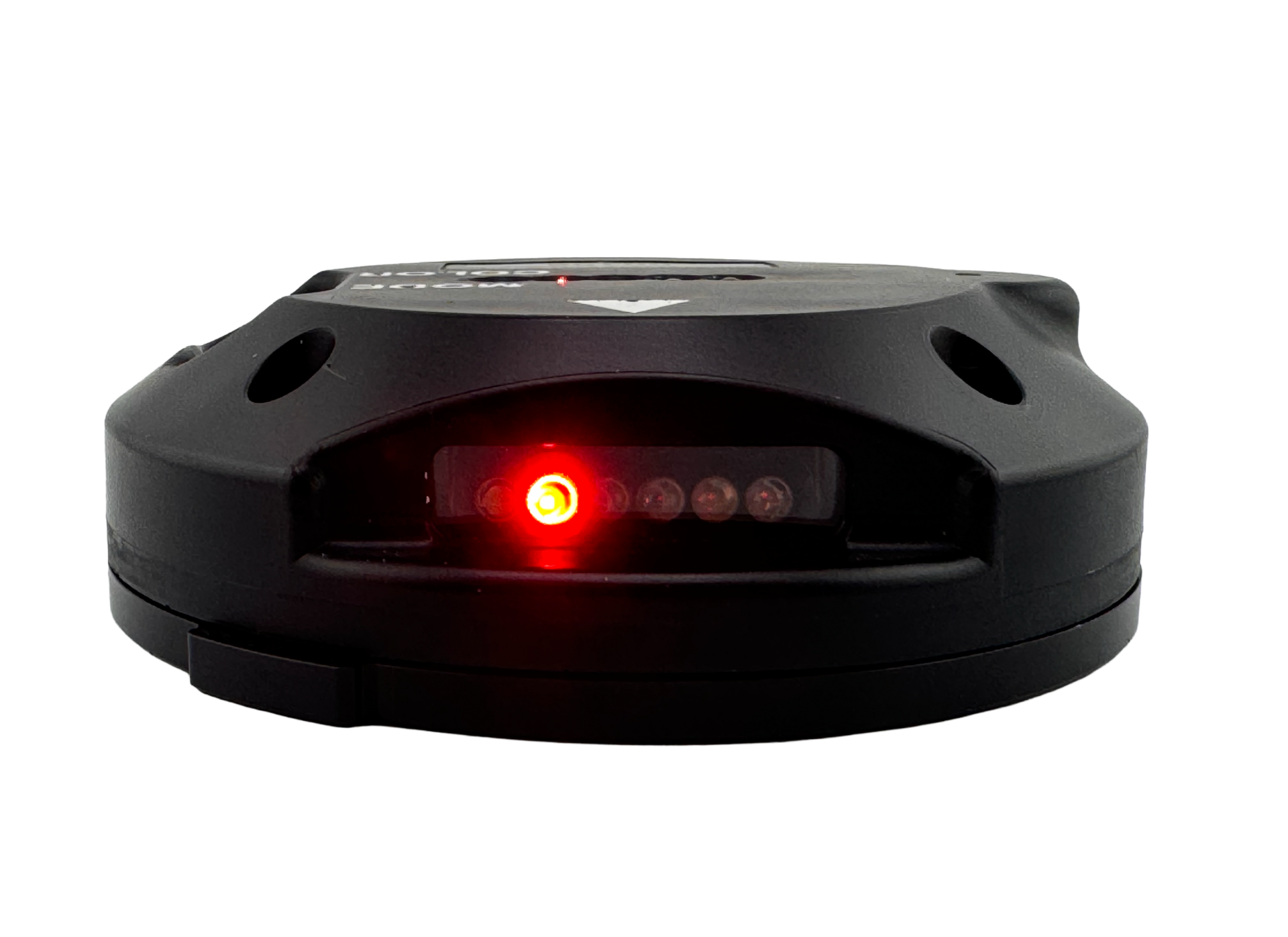
Two LED arrays (one horizontal and one vertical) have five different colors, (red, green, blue, white and IR). One array (forward facing), has 5 colors as well but has two IR LED’s versus just one as in the other two arrays.
Tie-Downs & Baseplate
The assembly can be anchored to the ground using two stakes included with a tie-down & baseplate.
Lodestar V2 Specifications
Description:
Remotely controlled, covert / overt battery powered multi-color LED airfield / LZ / DZ marking system with
steady, or flash modes of operation. The system is comprised of a base station unit that houses a mil spec tablet
that runs the control application software, base station antenna made of a mast unit and antenna element and
radio transmitter compartment, and V2 lights. Each light is composed of a main control board, switch board and
three LED array boards connected using state of the art rigid / flex technology for durability and reliability. Two
LED arrays, one (aft facing) horizontal and one vertical, have five different colors, (red, green, blue, white and
IR). One array (forward facing) has 5 colors as well but has two IR LED’s versus just one as in the other two
arrays. This allows the user to select this array when a higher level of IR output is required. The light unit is
micro-processor controlled and is programmable to provide any combination of modes / color options
customized to each customer’s needs. The base station user interface allows the user to visualize each light in a
GIS format, real time, with map data that is loaded onto the base tablet prior to each mission, control lights
individually and select color and mode for each as desired.
Dimensions:
Base Station Physical – W 16” x D 13” x H 5.5”
Weight 10 lbs. without 5590 internal battery, 13 lbs. with 5590 installed.
Base Antenna – The base station antenna is collapsible for storage and ease of transport.
In stowed configuration, that antenna is approximately L 18” x 4” diameter. The base station antenna weighs 2.75 lbs. Deployed, the base antenna is 9’ tall and is held upright with the use of three para-cord guy wires.
V2 Light
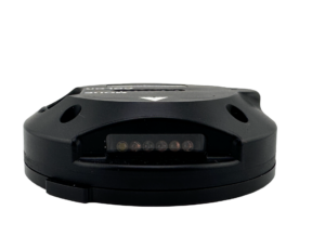
5” diameter and 1.5” tall
Light weighs 1.5 lbs. with 4 AA batteries installed.
The base station tablet has power built into it while the base station housing has (TBD) additional space for power in the form of a single BA-5590 battery for extended use.
Each V2 light has four (4) AA batteries (2.2 Ahr capacity typical). The electronics were designed with lithium battery chemistry as the desired type however, the unit will run as well on any alkaline cell just at a reduced endurance level.
Light Operational Modes:
1 – Standby (unit off with batteries installed)
2 – Continuous On
3 – Flash 500ms on 500ms off
Estimated Battery Life:
Standby (off) = 220,000 hrs. with 50 percent capacity remaining (220,000 hrs. = 25 yrs.)
(1.1Ahr/5ua) or advertised shelf life of battery, whichever comes first.
Continuous (color dependent) = IR – 9 hrs. / Red – 14 hrs. / White – 14 hrs. / Blue – 18 hrs. / Green – 18 hrs.
Flash (color dependent) = IR – 15 hrs. / Red – 22 hrs. / White – 26 hrs. / Blue – 38 hrs. / Green – 38 hrs.
Environmental limits:
Operational temperature = (-40C to +80C)
Storage Temperature = (-40C to +80C)
The battery life details represented above are using alkaline batteries. Alkaline battery chemistry will yield proportionately lower performance figures. Use of Lithium battery chemistry will at least double each figure represented in this spec sheet.
LEDs
Color Wavelength Viewing angle Brightness (mcd)
Blue 470 nm +/- 15 degrees 11,000
Red 626 nm +/- 15 degrees 16,500
Green 527 nm +/- 15 degrees 38,000
White full spectrum +/- 15 degrees 35,000
Infrared 850 nm +/- 16 degrees 10 mW/sr @ 20ma
There are two push button switches located on the exterior surface of the Lodestar housing labeled “MODE” and “COLOR”.
Manual Operation:
The mode button cycles the unit through the modes: These modes are customer specific and may be defined by each customer at the time of manufacture. A “mode” can be whether the light output is steady or flash, or the combination of arrays in use, IE – front and rear on with top off, top and rear with front off, top only…etc.)
The color button cycles the unit through the various colors (including IR)
• IR / Red / White / Blue / Green / Back to IR
Turn the unit on: This is defined by each customer and can be customized through programming at the time of manufacture. A typical “turn on” sequence might be to hold both Mode and Color buttons for 5 seconds. The unit will flash GREEN 3 times and go out after which the unit will default to IR / 3 array / steady mode. From here, pushing either the mode or color button individually will cycle the unit accordingly. Stop pushing all buttons when the desired color and mode are obtained.
Turn the unit off: Same as turning the unit on, this can be customer configured to each customers need / desires.
Remote Operation / Radio Controlled:
The main feature of the V2 system is the ability to control the system lights remotely through the base station unit via radio link. Each light has an onboard, micro-processor-controlled radio transmitter / receiver and GPS. The GPS collects location data, and the radio transmits this data, along with the status of each light, to the base station where it is displayed on a GIS interface allowing the operator to visualize where each light is located (real time) and see what mode and color the light is displaying and allow the user to control the mode and color as desired.
The V2 has been tested to determine the typical ranges that can be expected between the base station and the light units. The system is strictly line of sight (LOS) between the base and the lights and between each light. The maximum range between the base and the first light, or between any two lights is approximately 1 mile. To ensure reliable operation, the maximum distances between any two nodes (base or light) should be planned at 0.75 miles LOS. The system also has a mesh network capability that will allow the operator to cover “non-LOS” situations but must also be planned out so there is a link between all nodes. Using the mesh network, the system can span much greater distances. Ranges in excess of 15 miles can be obtained provided there is a link between nodes spaced at (nominally) 0.5 – 0.75 miles. A diagram is provided to illustrate the various scenarios.
The primary use for the V2 system is to establish / mark airfields, drop zones and landing zones, where the terrain is generally flat. It can, however, be used in hilly or even mountainous terrain as long as it is planned accordingly. Area studies with terrain analysis are essential in order to get reliable performance from the V2 system in non-line of sight scenarios.